
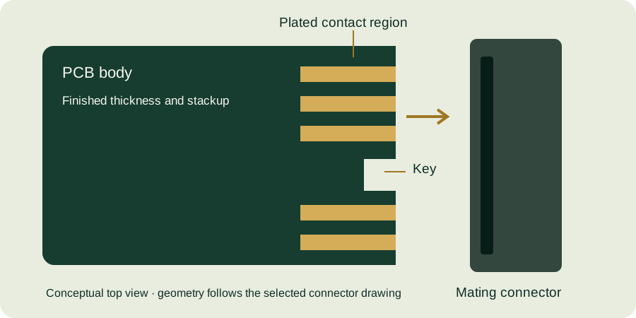
Define where the connector actually mates
A rigid-flex assembly combines areas with different mechanical roles. Identify whether the contact is on a rigid section, a stiffened flexible tail or another defined structure. These are not interchangeable interfaces. The connector drawing must match the actual finished section entering the connector, including thickness, stiffness, contact side and insertion direction.
Do not transfer rigid card-edge assumptions to flex tails
A flexible-circuit connector may use a different contact geometry and locking mechanism than a rigid card-edge connector. Confirm the selected component’s requirements before choosing a finish or adding a bevel. A stiffener can change thickness and handling, but it does not automatically make the tail equivalent to a qualified rigid board.
Separate insertion loads from bend requirements
Identify installation bends and any dynamic bending in normal service. Define the intended bend zone, construction, routing direction and mechanical support through an engineering review. Keep the connector region and any transition in stiffness visible in the drawing. Avoid a universal bend-radius rule without considering the complete layer structure and use case.
- Connector part number, contact orientation and applicable drawing revision.
- Finished mating thickness and tolerance, including stiffener and adhesive if present.
- Rigid and flexible region boundaries with mechanical datums.
- Contact finish and selective region on the correct side or sides.
- Installation versus dynamic bending conditions and any strain-relief features.
- Assembly, inspection and qualification requirements agreed for the application.
Make the prototype answer a mechanical question
Evaluate fit, insertion, retention and the installed shape using the intended connector and enclosure. Record any local deformation or stress near the transition. A successful continuity measurement on a flat sample does not establish performance after repeated bending or mating. Qualification should reflect the actual product’s use and be agreed before production.
Prepare a reviewable package
Include the full stackup, stiffener drawing, finished dimensions and assembly context. See the prototype guide for controlled revision handoff and the interface design guide for common card-edge documentation checks.
Have a drawing to review? Send your gold finger PCB requirements with the connector part number, quantities and any open questions. Files are optional.