
Inspection begins with an agreed requirement
A quality report is useful only when it answers the actual acceptance questions. Identify the critical properties of the gold finger interface before manufacture: final thickness, edge position, contact geometry, finish system, surface condition and electrical integrity. State how each property will be assessed and which records are required.
| Review area | Typical evidence to agree |
|---|---|
| Mechanical fit | Measured dimensions and tolerances tied to the drawing. |
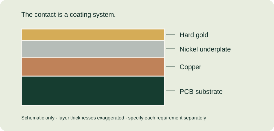
| Coating thickness | Method, locations, layer system, sampling and recorded results. |
| Contact surface | Defined criteria for damage, contamination and unacceptable defects. |
| Electrical integrity | Test coverage and acceptance requirements appropriate to the PCB. |
| Traceability | Revision, lot or order identity and approved deviations. |
| System reliability | Application-specific qualification of the mated assembly. |
Separate board acceptance from system qualification
A bare-board continuity test does not validate insertion life, vibration performance or a high-speed channel. Likewise, a connector qualification report is not proof that an unrelated board geometry is acceptable. Define which tests belong to fabrication acceptance and which belong to the product’s qualification program.
Plan the coating measurement
Agree how gold and nickel thickness will be measured and where the measurements represent the critical contact region. Ensure the method and setup are appropriate for the layer system. Decide whether the specification applies locally or by another defined basis; a panel average should not silently replace a local minimum.
Use visual inspection for the questions it can answer
Visual review can identify obvious damage, contamination or geometry concerns. It cannot reliably establish coating composition or thickness by color. Keep handling controls and packaging requirements aligned with the contact’s final use, and document any allowed cosmetic variation separately from functional acceptance.
Handle changes through a controlled review
If a material, finish, connector or drawing revision changes, assess the impact on previously accepted evidence. Record who approved any deviation and which build it applies to. Do not allow an informal email description to become an untracked replacement for the controlled fabrication drawing.
Prepare your acceptance request
Include the desired inspection records in the quotation inquiry so they can be reviewed with the manufacturing scope. The prototype planning guide helps identify which unresolved risks deserve targeted testing.
Have a drawing to review? Send your gold finger PCB requirements with the connector part number, quantities and any open questions. Files are optional.