
A connector’s card-thickness tolerance is an interval, not merely a nominal value. To check a proposed gold finger PCB, compare its full finished-thickness interval with the applicable connector requirement using the same measurement definition. Two specifications can share a nominal value while permitting different finished parts.
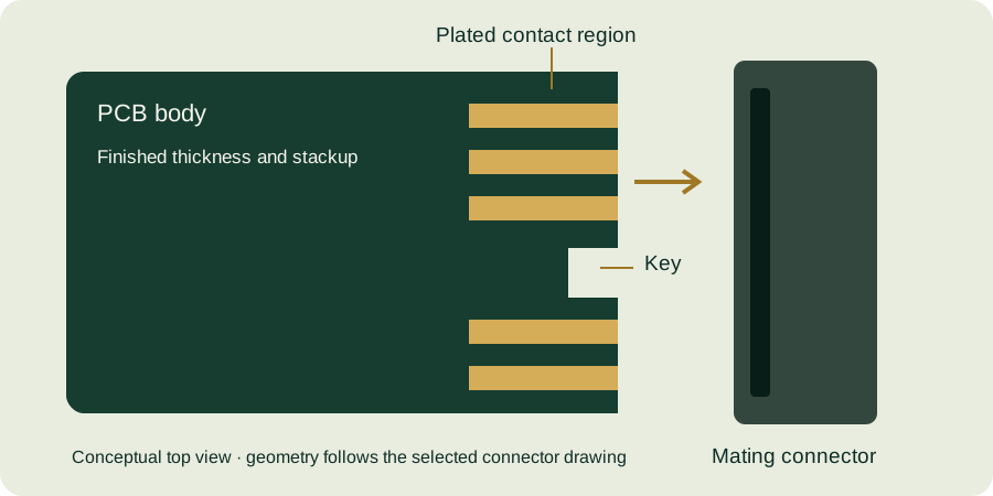
Convert the callouts into intervals
For a symmetric tolerance, subtract the allowance from the nominal to find the lower limit and add it to find the upper limit. A hypothetical 1.50 ± 0.10 mm specification therefore spans 1.40–1.60 mm. An asymmetric callout of 1.50 +0.08/−0.04 mm spans 1.46–1.58 mm. Keep both limits visible when reviewing alternatives.
For mixed units, convert the limits as well as the nominal. The NIST length-unit reference establishes the exact 25.4 mm per inch conversion; for example, an illustrative 0.060 ± 0.004 inch interval becomes 1.4224–1.6256 mm before any agreed rounding. Rounding the nominal alone can conceal a meaningful difference at an acceptance boundary.
Containment is stronger than overlap
| Illustrative interval | Lower limit | Upper limit | Conclusion against 1.40–1.60 mm |
|---|---|---|---|
| Candidate A | 1.42 | 1.58 | Entire stated range is inside |
| Candidate B | 1.45 | 1.65 | Some permitted boards exceed the upper limit |
| Candidate C | 1.35 | 1.55 | Some permitted boards fall below the lower limit |
These examples demonstrate interval arithmetic only. Candidate A is not automatically a qualified assembly: the surface convention, connector option, bevel, alignment and other requirements still need review. Candidates B and C should trigger a specification discussion even though their ranges overlap the connector interval.
Read notes and option tables with the dimension
A dimension can depend on contact count, housing option or another product selection. The applicable document must match the exact connector. Samtec’s HSEC1 mating-card drawing identifies the surfaces for its thickness dimension and provides separate geometry details. Do not borrow its values for an unrelated connector.
When a CAD model, product summary and controlled drawing appear inconsistent, record the discrepancy and ask the connector supplier which document governs the selected part. Avoid resolving the disagreement by choosing whichever limit is easiest to manufacture.
Agree how production evidence will be evaluated
Ask the board supplier to confirm the finished interval at the contact region, not simply the ability to purchase a nominal laminate thickness. Include the stackup, finished copper and contact-finish requirements in the review. A capability statement for a different construction may not answer the actual quotation request.
Define measurement locations and the treatment of uncertainty near a limit. A few favorable samples do not change the agreed tolerance for the rest of the lot. If a pilot build suggests the design requires revision, update the controlled requirement before ordering production.
Acceptance review checklist
- Match the tolerance to the exact connector option.
- Convert each callout into explicit lower and upper limits.
- Use consistent units and measurement surfaces.
- Check full interval containment rather than overlap alone.
- Record supplier agreement and required measurement evidence.
See the gold finger PCB design guide and inspection planning guide. Request a review of your finished-thickness limits with the applicable mating-card drawing attached.
Continue with our gold finger PCB design guide and engineering tools.