
A card-edge interface requirement should explain what must mate, what must be electrically connected, and what evidence will demonstrate acceptable operation. “Use gold fingers” leaves all three questions open. Before choosing a plating thickness or requesting a price, create a short interface record that the electrical designer, mechanical designer and fabricator can review together.
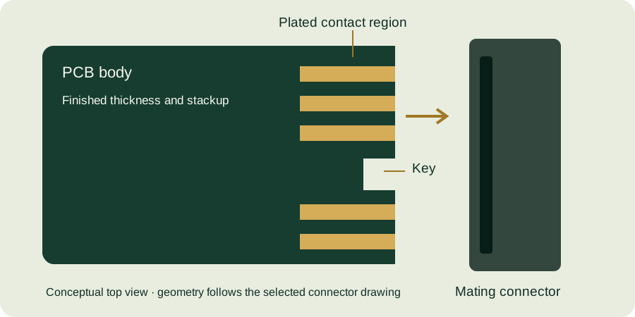
Start with the assembly boundary
Identify the removable card, the mating connector and the structure that positions them. Include any guide rails, front panel, fasteners or stops that constrain insertion. State whether the board is a prototype fixture, a replaceable service module or a product intended for repeated user operation. These descriptions do not determine a finish automatically; they identify questions that the subsequent design must answer.
Record the connector’s complete ordering code and the controlled drawing revision. Samtec’s HSEC1 document includes option-dependent layout information. It is a useful reminder that a connector family name alone may not identify the required geometry.
Build a requirement-to-evidence table
| Requirement group | Information to record | Evidence to plan |
|---|---|---|
| Mechanical fit | Card thickness, contact pattern, key, bevel and insertion constraints | Dimension report and assembly fit check |
| Electrical mapping | Contact identifiers, nets and viewing direction | Reviewed pin map and continuity checks |
| Contact finish | Finish regions, gold and underplate requirements, acceptance convention | Agreed inspection report |
| Use conditions | Expected handling, mating activity and environment | Application-specific qualification plan |
| Configuration control | Applicable files and approved exceptions | Release manifest and revision record |
Every unresolved cell needs an owner. A blank tolerance is not permission for production to choose one; a blank test condition is not proof that qualification is unnecessary. Mark unresolved items explicitly as open, with the decision needed before fabrication release.
Example: a replaceable measurement card
Consider a hypothetical measurement module that a technician removes during maintenance. The initial request says “double-sided gold fingers, standard thickness.” A useful revision identifies connector part A, drawing revision B, the two contact rows and their net assignments, a controlled thickness at the mating region, the required bevel detail and the enclosure stop that limits travel.
The requirements record also asks whether the system will be powered during removal. If that possibility exists, contact sequencing, system behavior and protection need separate engineering work. Longer fingers alone do not establish safe hot-plug operation. Keep that decision open until the responsible system designer defines and validates the behavior.
For maintenance frequency, record an expected usage scenario rather than inventing a lifetime from the gold thickness. A connector rating, a PCB finish specification and an assembled product’s service-life claim are different pieces of evidence. The qualification plan must explain how the actual interface will be assessed.
Write requirements that can be checked
Replace “good plating” with an approved finish callout and inspection method. Replace “fits the connector” with controlled interface dimensions and an assembly check. Replace “same as last time” with a specific released revision. Avoid adding tighter limits merely because they look more precise; unnecessary restrictions can create cost without answering an application need.
A requirement should also state its scope. A thickness measurement away from the connector may not answer a contact-region requirement. A visual sample may demonstrate appearance but cannot replace all dimensional or finish evidence.
Before sending the first inquiry
- Identify both mating parts and the relevant drawing versions.
- Attach the pin map with explicit top and bottom views.
- Define mechanical constraints imposed by the enclosure.
- Separate confirmed finish requirements from open decisions.
- List intended use conditions without unsupported lifetime claims.
- Assign each open issue to a decision owner.
Use the design-readiness checklist alongside the interface design guide. Then request a specification review with your current drawing and a clearly labeled list of open requirements.
Continue with our gold finger PCB design guide and engineering tools.